This was actually one of the first LED conversions that I did, but I never posted it because I’ve been wanting to re-do it to make it nice and pretty. The problem is that it works so well that I haven’t been pressed to make any changes. This being the case I’m posting the modification as it is until I decide to change it.
When we bought our 1993 Honda Civic a few years ago one of the first things I noticed was that the dome light was terribly dim. I thought it was a bad bulb, so I replaced it, but that didn’t make any difference. It was a few months later that I started getting into LEDs so I created a really poorly done prototype. It was three 3mm LEDs with a few resistors. The problem (as mentioned on other pages of this site) is that the voltage from a car battery can fluctuate quite a bit from 11 – 14 volts. LED’s really can’t handle this change so my first model was designed for the worst case scenario of 14 volts. What happened was when the car wasn’t running the alternator the LEDs were pretty dim.
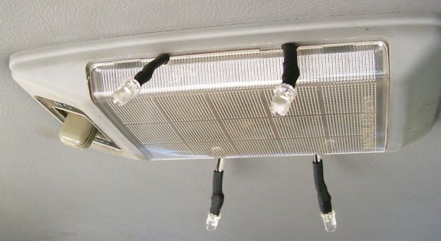
I promptly replaced this model once I learned about current regulating circuits like the ones mentioned here. I also redesigned the light because it was hard for the LEDs to illuminate the car through the dome light plastic. I wanted light that I could re-position to different parts of the car (for reading, spot lighting a section or to remove light from another. I cut tiny little “V”s into the plastic and used solid strand copper wire attached to the LEDs with shrink tube. Here is what it looks like:


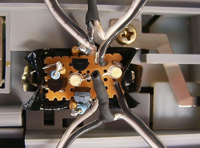
Above is a shot of the circuit. You’ll see that I used perf board and have two 3mm LEDs in the middle for a little extra light. I cut a paperclip and bent it in a “V” then soldered it to the board to make the contacts to fit where the bulb use to be. I’ve got some electrical tape on the back to protect the soldering.